This case study intends to model a simulator for the FIRA Mirosot Robot soccer competition. This competition involves two teams of five autonomous robots playing a game similar to soccer. This is a classical example where real-time coordination is required. It constitutes a well-known benchmark for several research fields, such as MAS, image processing and control.
Contents |
System Requirements Analysis
Domain Requirements Description
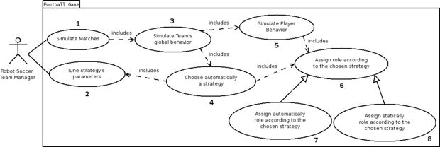
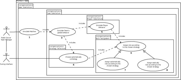
Figure 1 details the use cases associated to the development of a simulator for the FIRA Robot Soccer cup. Eight use cases and one actor have been identified, each use case has been numbered in order to facilitate the explanations in the following activities. The actor represents the user of the simulator who can simulate matches and tune the strategy of each team. Simulating a match implies the simulation of two autonomous teams which can choose their own strategy and are responsible for simulating the individual robots behavior.
Problem Ontology Description
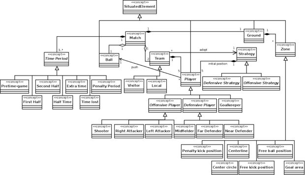
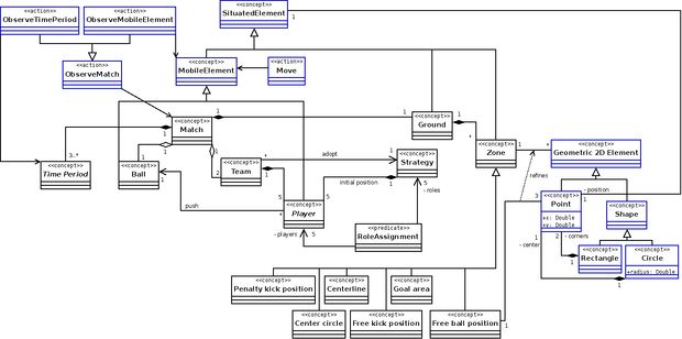
The ontology associated to the domain of the FIRA Robot soccer is partially detailed in Figure 2. This ontology represents knowledge about robot soccer matches such as how time periods are handled, the different mobile (and thus situated) elements, rules handling, etc.
Organization Identification
From the use cases presented in the DRD activity different approaches could be used to group use cases and identify organizations. The first task consists in identifying which functionalities will be designed using an agent-oriented approach and which ones with a traditional object-oriented approach. In this example, we have decided to design functionalities of use case 2 with an OO approach (see Figure 1). In this situation, we extract this use case from the agent-oriented part of the system, and we represent it as a new actor, called Tuning interface. The part of the system corresponding to this use case will be designed separately using a classical object-oriented software process like for instance UP. Concerning the other use cases, three possible partitions can be studied, each one corresponding to a different point of view on the system:
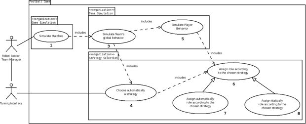
- Functional/Behavioral approach: Three main functional areas are identified, and an organization is associated to each one. Firstly the global system is itself associated to an organization Game Simulation managing use case 1 (see Figure 3) The behavior simulation is associated to a second organization called Team Simulation and in charge of use cases 3 and 5. And finally strategy determination is associated to an organization called Strategy Decision grouping use cases 4,6,7 et 8. The result of the organization identification with a such approach is described in Figure 3.
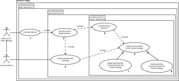
- Structural/Ontological approach: This partition is based on the hierarchical decomposition of the ontology. Uses cases referring to ontological concepts of the same level are grouped. At the top level of the hierarchy, an organization named Game Simulation grouping use case 1 is defined and it is related to the highest concept in the ontology, Match. Then use cases 3 and 4, referring to Team and Strategy are assigned to a unique organization and at the third level the organization Player Simulation is introduced to deal with use cases 5,6,7 and 8, attached to sub-concepts of Player in the ontology. It is interesting to note that this approach introduced a nice hierarchy of organizations. This case is detailed in Figure 4.
- Multi-view approach: The multi-view approach consists in merging the various points of view we can have on the system (including the two previous ones). This approach respects the hierarchical nature of the system revealed by the ontological approach but it clearly separates use cases attached to different system functionalities. We have leaned for the last solution where granularity of functionalities and the different levels of abstraction present in the system are best respected. This case is detailed in Figure 5.
Interactions and Role Identification
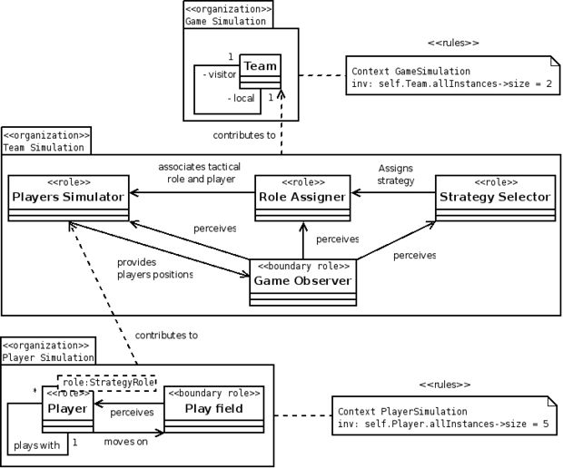
According to the previously identified hierarchy of organizations, the objective is now to decompose each organization and precise the behavioral contribution of sub-level organizations to an upper-level organization. In this example we used a top-down behavioral decomposition and studied at each level if it’s really necessary to decompose each role with a sub-level organization or not. Figure 6 describes the result of this decomposition: the various organizationals and their respective contributions.
At the top of the hierarchy, the Game Simulation organization is decomposed using only one interaction and one role Team. An OCL constraint is added to specify that only two instances of this role are allowed in each instance of this organization. This role is in charge of simulating the behavior of a robots soccer team. Its complexity at this level is considered as too high and it will be decomposed into smaller interacting behaviors.
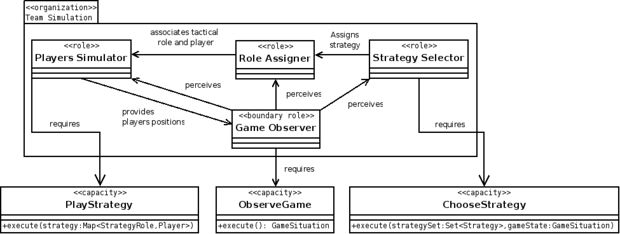
At the second level, the organization Team Simulation is decomposed in four roles, three roles representing the contributions of previously identified sub-level organizations and an environmental role useful to provide required information about the Game Situation (players and ball position, score, etc). The Strategy Selector role is in charge of determining the best strategy to adopt according to the current situation. Each strategy correspond to a distribution of strategy roles like goalkeeper, near-defender, midfielder, shooter, etc. among the different players. Each robot soccer team is composed of five players. Applying a strategy thus consists in assigning to each player one of the five roles defined by the strategy. The association between player and role defined by the strategy is done by the Role Assigner role. The Players Simulator role is in charge of simulating the behavior of the various players according to the chosen strategy. The global state of the game (players and ball positions, score, time, etc.) is maintained by the boundary role Game Observer. This role is also in charge of providing required perceptions to the others.
According to the work products of the organization identification activity, each of the three first roles is associated to a use case and should be decomposed into sub-organizations. But at this step one can already decide that the behaviors granularity is sufficiently detailed. The Role Assigner and Strategy Selection role are considered as sufficiently detailed, the Players Simulator role may be decomposed. This reveals a new level in the hierarchy, and the Player Simulation organization is introduced. It defines the Player role in charge of simulating the behavior of a robot playing soccer and one boundary role representing the Play Field and maintaining the state of the game at this level of abstraction.
Scenario Description
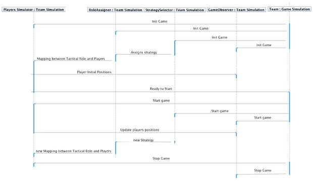
A scenario associated to the Team Simulation Organization is described in Figure 7. Each role has of its own lifeline. The upper level is represented in this diagram via an actor called Team:Game Simulation. This scenario consists in the Team sending initialization messages. The StrategySelector then decides a strategy which is sent to the RoleAssigner which, in turn, decides of a role assignment and sends it to the Player. Robots are then situated on the field and the Player sends a ready-to-start message to the Team. The game begins when the user starts the match, the role Team then forward this information using the start message.
Role Plan
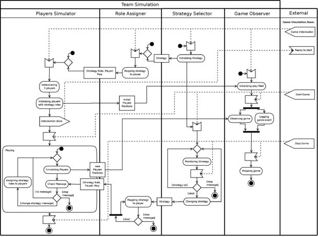
The description of role plans associated to the Team Simulation organization is presented in Figure 8. The activity diagram is partitioned according to the different roles of the organization, a supplementary partition line is added to represented the part of the system external to the designed organization. Interactions with this external part are represented by adopting an event-driven perspective.
Capacity Identification
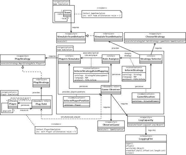
Considering the previous example and specifically the Team Simulation Organization, it is possible to note that, in this organization the Strategy Selection role has to identify the best strategy for a given game situation. This choice can typically be implemented under various perspectives, even decomposed using a sub-level organization. This can be extracted from the role behavior by creating a specific capacity called ChooseStrategy. In the same way the Game Situation role is able to maintain the information related to state of the game (player and ball positions, score) and to check if game rules are respected. This behavior thus requires the possibility to observe the game. This observation mechanism can be implemented in different ways and it always requires specific rights. A capacity can also been designed for this aspect. Figure 9 summarizes the different capacities identified in this organization.
Agent Society Design
Solution Ontology Description
Figure 10 describes a part of the Solution Ontology associated to our example of the FIRA Robot Soccer Simulator. This ontology is a refinement of the Problem Ontology previously described in the Domain Requirements Description phase. New concepts related to the description of elements localization in the play field, together with some actions and predicates have been introduced. For instance actions related to game observation are introduced due to the identification of the ObserveGame capacity in the Team Simulation organization.
Communication Ontological Description
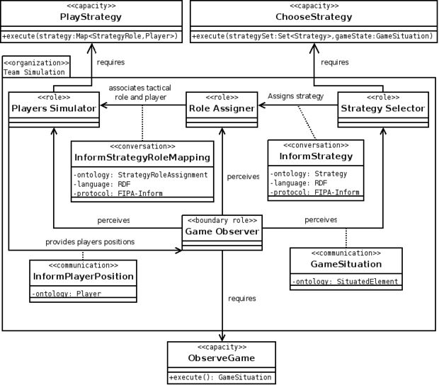
Let’s now consider the Team Simulation organization of our example. In this organization six interactions have been identified. Two of them may be modeled as a conversation. For instance, the interaction between Players Simulator and Role Assigner may be considered as a conversation respecting the FIPA Inform Communicative Act [30], manipulating the Strategy Role Assignment predicate previously defined in the Solution ontology and adopting the RDF (Resource Description Framework) content language [28]. Figure 11 describes several of the communications and conversations of the Team Simulation organization.
Role Behavior Description
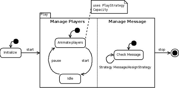
Figure 12 describes the state-chart associated to the Players Simulator role of the Team Simulation organization. It corresponds to the refinement of the behavior described by the role plan in the previous phases. The default state is initialize and then after a start event the role simultaneously manages players and messages. Managing players consists in animating players except if a pause event occurs. Managing messages consists in looking for new messages dispatching a new strategy.
Organization Dependencies Description
Figure 13 describes capacities, services and resources in relation with the three organizations involved in the model of the Robot Soccer Simulator case study. Contributions of each organization to the upper level have been detailed by using a capacity and the associated service, e.g. SimulateTeamBehavior or PlayStrategy. One resource has been identified, it represents a logging file, and the Log capacity has been created to manage it. It is interesting to note that this capacity does not need a service realization because the corresponding functionality is internal to the GameObserver role that does not need to publish it as a service. This capacity does not represent a contribution between organization but a competence required by a role to access to one of its dependencies.
Role Constraints Identification
In the presented case study, the environment is simulated by using one single agent. This implies that all boundary roles of the application have to be played by a single agent. This is described in Figure 13, by a constraint between the two identified boundary roles (Play Field and Game Observer). This type of constraint will have relevant consequences on the structure of the final system as it will be detailed in next section.
Holarchy Design
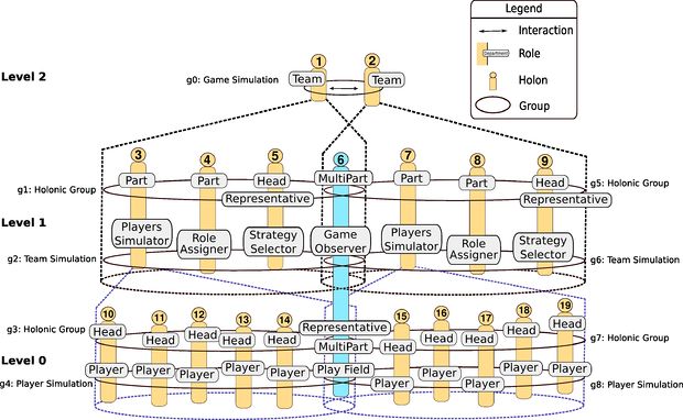
The final structure of the holonic solution dealing with our Robot Soccer simulator is presented in Figure 14. At the level 2 of the holarchy two superholons 1 and 2 plays the role Team in the group g0 : Game Simulation. This denomination indicates that group g0 is an instance of the Game Simulation organization. As such, members involved in the group play one of the roles defined in this organization. Each of them contains an instance of the Team Simulation organization g2 and g6. Each composed holons (1, 2, 3, 7) contains a holonic group defining its governmental structure. Each Team Holon dispose of a simple government type inspired by the monarchy government type. The rule is that the holon playing the Strategy Selector role is automatically promoted Head and Representative of others members. The part holons 3 and 7 playing the Players Simulator role are decomposed, and each of them contains an instance of the Player Simulation organization. Their government is inspired by the apanarchy government type where each member is involved in the decision process (everybody is head). The atomic holon 6, playing the MultiPart role, is shared in two couples of super-holons (1, 2) and (3, 7). This holon constitutes the environmental part of the application and plays all the boundary roles in agreement with the description made in the Role Constraints Identification phase.
Implementation and Deployment
Holon Architecture Definition
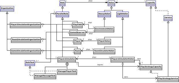
Figure 15 depicts a part of the Holons architecture implied in the implementation of our Robot Soccer Simulator example. In this example we have opted for a static approach. For each architecture identified in the Holarchy Design activity, a specific holon is designed. Three holon architectures and three organisations are partially described in the class diagram. Only the role PlayersSimulator is described in terms of RoleTask. Classes already introduced in the solution domain correspond to class provided by the Janus platform that are refined to define problem dependent artifacts.
Code Production of Organizations and Roles
Part of the code of the PlayersSimulator role of our Robot soccer simulator is reported in Figure 16. This role class inherits from the Janus ParallelRole class that provides an abstract definition of role with a task-composed behavior. It also provides the definition of the Task interface. The behaviour of the PlayersSimulator role is decomposed into two different tasks: the Manage-PlayersTask and ManageMessageTask ones. The behavior of each of these tasks was previously described in the Role Behavior Description using a state-chart. This corresponding code representation of this task behavior is putted inside execute method.
package janus.demos.robotsimulator.teamsimulation;
/* ... */
public class PlayersSimulator extends ParallelRole {
// ... Role Attributes ...

   public PlayersSimulator() {
        super();
        //Define the capacity required by the role
        List<Class<? extends Capacity>> requiredCapacities = new LinkedList<Class<? extends Capacity>>();
        requiredCapacities.add(PlayStrategyCapacity.class);
        HasAllRequiredCapacitiesCondition capCondi =  new HasAllRequiredCapacitiesCondition(requiredCapacities);


        //Define the access conditions
        addObtainCondition(capCondi);
    }


/* ... */


    public void initTasks() {
        //Definition of the task that compose the role behavior
        this.addTask(new ManagePlayersTask());
        this.addTask(new ManageMessageTask());
    }


//The heart of role behavior
    public void behavior() {
        super.scheduleTasks();
    }


//Definition of the first task.
    private class ManagePlayersTask implements RoleTask {
        private int current = 1;  // The current state of the task
        public ManagePlayersTask() { }


        //Task Behavior
        public int execute() {
            switch (current){
            /*...*/

            // This method correspond to the java translation of the state-chart corresponding to the designed task behavior
            default : return 0;
            }
        }
    }
/* ... */
}
Code Production of Holons
Figure 17 depicts part of the code of the PlayersSimulatorHolon Holon. This holon class inherits from the Janus LightHolon class that provides an abstract definition of non threaded holon. As regards the three basic methods used to govern the holon’s life-cycle, in this example, activation corresponds to the definition of the capacities that the holon owns and the request of roles that have to be played by the current holon. Execution deals with scheduling of holon’s roles. And finally the previously acquired roles are released during the termination phase.
package janus.demos.robotsimulator.holon;
/* ... */
public class PlayersSimulatorHolon extends LightHolon {
// Attributes of the holon

    private GroupAddress TeamGA;

//First step of the holon life cycle: the activation
    public void activate() {
        //Definition of the capacity of the holon and their corresponding implementations
        addCapacity(PlayStrategyCapacity.class, new PlayStrategyCapacityImpl(this));

        //Creation of a group implementing the TeamSimulationOrganization organization or request to access to an already existing one
        TeamGA = getOrCreateGroup(TeamSimulationOrganization.getInstance());
        println("About to request role "+TeamGA);

        //Request to access to the PlayersSimulator role in the group TeamGA
        if(requestRole(PlayersSimulator.class,TeamGA)){
            //Journalisation d'informations
            getLogger().info("role PlayersSimulator assigned");
        }
    }

//Last step of the holon life cycle: the termination

   public void end() {
        //Request to leave the role PlayersSimulator

        if(leaveRole(PlayersSimulator.class,TeamGA)){
            getLogger().info("role TeamSimulationOrganization:PlayersSimulator disassigned");
        } else {
            getLogger().error("Pb during dis-assignation of TeamSimulationOrganization:PlayersSimulator role");
        }
    }
}
Deployment Configuration
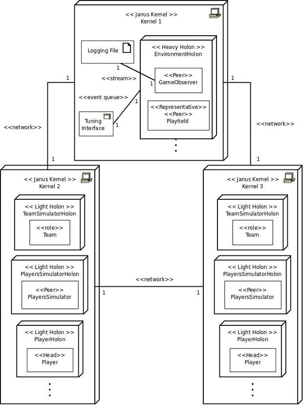
Figure 18 partially describes the deployment configuration associated to our Robot Soccer simulator example. Three Janus kernels are used to distribute the application over the network: one kernel is used for each of the two TeamSimulatorHolon holons (and their associated members) and the last one is used for the shared environment holon and the graphical user interface. In our example we assume that all kernels already have installed all the classes associated to each organization involved in the designed solution.

